ardupilot@天穹飞控 计算遥杆控制量到加速度/速度
时间:2023-09-22 04:37:02
目录
文章目录
- 目录
- 摘要
- 1. 获得遥控器横滚/俯仰输入量转换为角度量
- 2. 在飞机的地理坐标系下,目标水平滚动/俯仰角控制量转换为加速度和预测加速度
- 3.期望加速度和预测加速度
- 4. 如何使用预期速度?
-
- 1.更新目标位置
- 2.控制前馈速度
- 5.获得姿态控量
- 6.控制天空飞控位置实现逻辑逻辑
-
- 1.遥杆变化转换为无人机速度控制。
摘要
本节主要记录ardupilot 计算遥控器水平滚动,将俯仰控制量转换为目标预期加速度和预测加速度,然后将其转换为预期加速度,并结合天空飞行控制代码获取目标速度。写这篇文章的目的,ardupilot的loiter刹车不是很好,希望能找到更好的loiter制动控制效果,欢迎批评指正,一起讨论!在查看代码之前,请注意两个坐标系、身体坐标系和地理坐标系,以及哪个坐标系控制量。
1. 获得遥控器横滚/俯仰输入量转换为角度量
///定义目标水平滚动角度 float target_roll, target_pitch; //---- apply SIMPLE mode transform to pilot inputs update_simple_mode(); ///将飞行员转换到倾斜角度--- convert pilot input to lean angles get_pilot_desired_lean_angles(target_roll, target_pitch, loiter_nav->get_angle_max_cd(), attitude_control->get_althold_lean_angle_max()); 关键函数是get_pilot_desired_lean_angles(target_roll, target_pitch, loiter_nav->get_angle_max_cd(),
attitude_control->get_althold_lean_angle_max());
- 该函数的形参:target_roll, target_pitch, loiter_nav->get_angle_max_cd(),
attitude_control->get_althold_lean_angle_max()
void Mode::get_pilot_desired_lean_angles(float &roll_out, float &pitch_out, float angle_max, float angle_limit) const {
             //油门故障检查------ throttle failsafe check     if (copter.failsafe.radio || !copter.ap.rc_receiver_present)     {
                 roll_out = 0;         pitch_out = 0;         return;     }     ///获得横滚和俯仰输入----- fetch roll and pitch inputs     roll_out = channel_roll->get_control_in() pitch_out = channel_pitch->get_control_in(); //限制最大倾斜角度----- limit max lean angle angle_limit = constrain_float(angle_limit, 1000.0f, angle_max); // scale roll and pitch inputs to ANGLE_MAX parameter range //将横滚和俯仰输入缩放到角度_最大参数范围 float scaler = angle_max/(float)ROLL_PITCH_YAW_INPUT_MAX; //最大不超过45度 roll_out *= scaler; pitch_out *= scaler; //做循环限制------ do circular limit float total_in = norm(pitch_out, roll_out); if (total_in > angle_limit) {
          float ratio = angle_limit / total_in; //2/2gen2 roll_out *= ratio; pitch_out *= ratio; } // do lateral tilt to euler roll conversion //进行横向倾斜到欧拉俯仰角转换,范围不超过【-17 +17】度 //这里进行的处理应该是:横滚角度=artan(rzy,rzz)=arctan(sin(r)cos(p)/cos(r)/cos(p)) //roll=arctan(sin(r)cos(p)/cos(r)/cos(p))=arctan(cosp*tanr/1)也就是把cosp设置最大值,roll有最小值 roll_out = (18000/M_PI) * atanf(cosf(pitch_out*(M_PI/18000))*tanf(roll_out*(M_PI/18000))); // roll_out and pitch_out are returned }
到这里得到了遥杆横滚+俯仰输入量到目标横滚角+俯仰角。
2. 目标横滚/俯仰角度控制量转换成飞行器的地理坐标系下加速度及预测加速度
void AC_Loiter::set_pilot_desired_acceleration(float euler_roll_angle_cd, float euler_pitch_angle_cd, float dt)
{

    // Convert from centidegrees on public interface to radians
	//从公共界面上的cm度转换为弧度
    const float euler_roll_angle = radians(euler_roll_angle_cd*0.01f);    //转换成了弧度
    const float euler_pitch_angle = radians(euler_pitch_angle_cd*0.01f);  //转换成了弧度

    //convert our desired attitude to an acceleration vector assuming we are hovering
    //假设我们在悬停,将我们想要的姿态转换成加速度矢量
    const float pilot_cos_pitch_target = constrain_float(cosf(euler_pitch_angle), 0.5f, 1.0f);  //限制在0-60度
    //右侧的加速度,这个直接根据https://www.sohu.com/a/243549866_466960实现
    const float pilot_accel_rgt_cms = GRAVITY_MSS*100.0f * tanf(euler_roll_angle)/pilot_cos_pitch_target;
    //前进的加速度
    const float pilot_accel_fwd_cms = -GRAVITY_MSS*100.0f * tanf(euler_pitch_angle);

    //旋转加速度矢量到地理坐标系lat/lon坐标系------ rotate acceleration vectors input to lat/lon frame
    _desired_accel.x = (pilot_accel_fwd_cms*_ahrs.cos_yaw() - pilot_accel_rgt_cms*_ahrs.sin_yaw());
    _desired_accel.y = (pilot_accel_fwd_cms*_ahrs.sin_yaw() + pilot_accel_rgt_cms*_ahrs.cos_yaw());

    // difference between where we think we should be and where we want to be
    //我们认为我们应该去的地方和我们想要去的地方之间的差异
    Vector2f angle_error(wrap_PI(euler_roll_angle - _predicted_euler_angle.x), wrap_PI(euler_pitch_angle - _predicted_euler_angle.y));
    // calculate the angular velocity that we would expect given our desired and predicted attitude
    //根据我们期望和预测的姿态,计算出我们期望的角速度
    _attitude_control.input_shaping_rate_predictor(angle_error, _predicted_euler_rate, dt);
    // update our predicted attitude based on our predicted angular velocity
    //根据我们的预测角速度更新我们的预测姿态
    _predicted_euler_angle += _predicted_euler_rate * dt;

    // convert our predicted attitude to an acceleration vector assuming we are hovering
    //假设我们在悬停,将预测的姿态转换为加速度矢量
    const float pilot_predicted_cos_pitch_target = cosf(_predicted_euler_angle.y);
    const float pilot_predicted_accel_rgt_cms = GRAVITY_MSS*100.0f * tanf(_predicted_euler_angle.x)/pilot_predicted_cos_pitch_target;
    const float pilot_predicted_accel_fwd_cms = -GRAVITY_MSS*100.0f * tanf(_predicted_euler_angle.y);

    // rotate acceleration vectors input to lat/lon frame
    //旋转输入到lat/lon框架的加速度矢量
    _predicted_accel.x = (pilot_predicted_accel_fwd_cms*_ahrs.cos_yaw() - pilot_predicted_accel_rgt_cms*_ahrs.sin_yaw());
    _predicted_accel.y = (pilot_predicted_accel_fwd_cms*_ahrs.sin_yaw() + pilot_predicted_accel_rgt_cms*_ahrs.cos_yaw());

}
这个函数有几个关键点需要注意:
1.目标横滚角,俯仰角说的是机体坐标系下的,需要把这个目标角度转换成机体坐标系下的加速度量。重点是下面公式
    //convert our desired attitude to an acceleration vector assuming we are hovering
    //假设我们在悬停,将我们想要的姿态转换成加速度矢量
    const float pilot_cos_pitch_target = constrain_float(cosf(euler_pitch_angle), 0.5f, 1.0f);  //限制在0-60度
    //右侧的加速度,这个直接根据https://www.sohu.com/a/243549866_466960实现
    const float pilot_accel_rgt_cms = GRAVITY_MSS*100.0f * tanf(euler_roll_angle)/pilot_cos_pitch_target;
    //前进的加速度
    const float pilot_accel_fwd_cms = -GRAVITY_MSS*100.0f * tanf(euler_pitch_angle);
这个是如何实现的?
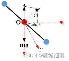
上面代码核心实现:把飞行员操作输入的目标横滚角及目标俯仰角度转换成飞行器NED坐标系下的的目标加速度值,这里假设轴受力平衡,即在轴上保持静止,目标高度不变。则其受力如下图所示。这里把无人机看成质点,若想让无人机在NED坐标系轴保持静止,需要的垂直拉力刚好抵消重力,外力的分力产生维持轴上产生向前的加速度及轴上产生向右的加速度。
对于上面的正负号,不一致,原因在于ardupilot规定 横滚左负,右正;俯仰,上正,下负。
2.得到机体坐标系下的加速度后,我们还需要得到无人机地理坐标系下的速度信息。
3.加速度预测加速度
这里需要注意的是
_predicted_euler_angle.x表示横滚角,_predicted_euler_angle.y表示俯仰角,这里的转换公式和上面一样,这里不在进行讲述。
总结:
这里我们需要问这里是做什么?我们得到了两个加速度信息,一个是期望加速度,一个是预测加速度,这两个对后续的期望速度都有影响,同时根据期望加速度进行刹车相关处理,预测加速度对期望速度进行更新。
3.期望加速度及预测加速度更新期望速度
calc_desired_velocity(dt)
void AC_Loiter::calc_desired_velocity(float nav_dt)
{

	static Vector2f  lastVelCtlTarget;
    bool desired_accel_is_zero=0; //定义加速度
    bool desired_vel_is_zero=0;   //定义速度
    //新增刹车增量
    float brake_increment=0;
    float ekfGndSpdLimit, ekfNavVelGainScaler;

    //导航的更新实际
    ym_log_nav_dt=nav_dt; //这个值大概在0.0015-0.0025

    AP::ahrs_navekf().getEkfControlLimits(ekfGndSpdLimit, ekfNavVelGainScaler);
    //ekf地速限制时间
    ym_log_ekfGndSpdLimit=ekfGndSpdLimit; //400
    //loiter模式下速度
    ym_log_speed_cms=_speed_cms;//1200
    //计算悬停速度限值,该限值为悬停速度设定值的最小值
    //参数和EKF设置的值,以观察光流限制
    float gnd_speed_limit_cms = MIN(_speed_cms, ekfGndSpdLimit*100.0f); //最小地速限制
    gnd_speed_limit_cms = MAX(gnd_speed_limit_cms, LOITER_SPEED_MIN);
    //地速限制
    ym_log_gnd_speed_limit_cms=gnd_speed_limit_cms; //1200
    //飞行最大加速度
    float pilot_acceleration_max = GRAVITY_MSS*100.0f * tanf(radians(get_angle_max_cd()*0.01f));

    //检查nav_dt 范围------ range check nav_dt
    if (nav_dt < 0)
    {

        return;
    }
    //设置最大速度
    _pos_control.set_max_speed_xy(gnd_speed_limit_cms);
    //设置最大加速度
    _pos_control.set_max_accel_xy(_accel_cmss);
    _pos_control.set_leash_length_xy(LOITER_POS_CORRECTION_MAX);

    //get loiters desired velocity from the position controller where it is being stored.
    //从被存储的地方,获取位置控制器获取悬停所需速度。
    const Vector3f &desired_vel_3d = _pos_control.get_desired_velocity();
    Vector2f desired_vel(desired_vel_3d.x,desired_vel_3d.y);

    // update the desired velocity using our predicted acceleration
    //使用预测加速度更新我们的目标速度,实时更新
    desired_vel.x += _predicted_accel.x * nav_dt;
    desired_vel.y += _predicted_accel.y * nav_dt; //【-292 294】

    ymv_log_predicted_speed_x=_predicted_accel.x * nav_dt;          //速度x
    ymv_log_predicted_speed_y=_predicted_accel.y * nav_dt;          //速度y

    log_desired_vel_x=desired_vel.x;          //目标速度x 【-401 351】
    log_desired_vel_y=desired_vel.y;          //目标速度y 【-832 766】
    //下面是刹车相关处理
    Vector2f loiter_accel_brake; //查查加速度
    float desired_speed = desired_vel.length(); //计算速度长度


    //判断速度是否等于0
    desired_vel_is_zero=is_zero(desired_speed);
    //判断速度长度是否为零
    if (!desired_vel_is_zero)//当有目标速度时执行
    {

    	//归一化处理
        Vector2f desired_vel_norm = desired_vel/desired_speed;

        // TODO: consider using a velocity squared relationship like
        // pilot_acceleration_max*(desired_speed/gnd_speed_limit_cms)^2;
        // the drag characteristic of a multirotor should be examined to generate a curve
        // we could add a expo function here to fine tune it
        //todo:考虑使用速度平方关系
        //飞行员加速度最大值*(期望速度/地面速度极限值)^2;
        //应检查多转子的阻力特性,以生成曲线
        //我们可以在这里添加一个expo功能来进行微调
        //calculate a drag acceleration based on the desired speed.
        //根据所需速度计算阻力加速度
        float drag_decel = pilot_acceleration_max*desired_speed/gnd_speed_limit_cms;  //一半的阻力限制
        // calculate a braking acceleration if sticks are at zero
        //如果摇杆为零,计算刹车加速度
        float loiter_brake_accel = 0.0f; //如果摇杆为零,计算一个刹车加速度
        //当目标加速度是零

        desired_accel_is_zero=_desired_accel.is_zero();
        //判断加速度是否等于0
        if (desired_accel_is_zero) //开始进行刹车,否则不进行刹车操作
        {

            if ((AP_HAL::millis()-_brake_timer) > _brake_delay * 1000.0f)
            {

            	//计算刹车增益
                float brake_gain = _pos_control.get_vel_xy_pid().kP() * 0.5f; //刹车增益是0.5
                //计算刹车加速度 //float error, float p, float second_ord_lim, float dt
                //得到悬停刹车加速度范围
                loiter_brake_accel = constrain_float(AC_AttitudeControl::sqrt_controller
                		(desired_speed, brake_gain, _brake_jerk_max_cmsss, nav_dt), 0.0f
						, _brake_accel_cmss);
            }
        } else
        {

            loiter_brake_accel = 0.0f;
            _brake_timer = AP_HAL::millis();
        }


        //增加刹车增量,也就是刹车加速度
        brake_increment=loiter_brake_accel-_brake_accel;
        //计算刹车加速度
        _brake_accel += constrain_float(brake_increment, -_brake_jerk_max_cmsss*nav_dt,
        		_brake_jerk_max_cmsss*nav_dt);
        // update the desired velocity using the drag and braking accelerations
        //使用阻力和制动加速度更新所需速度
        //整体合理阻力
        desired_speed = MAX(desired_speed-(drag_decel+_brake_accel)*nav_dt,0.0f);

        //归一化处理
        desired_vel = desired_vel_norm*desired_speed; //得到实时运动的速度
    }


    //增加刹车到期望加速度里面
    _desired_accel -= loiter_accel_brake;

    // Apply EKF limit to desired velocity - this limit is calculated by the EKF and adjusted as required to ensure certain sensor limits are respected (eg optical flow sensing)
    //申请EKF限制到目标速度-
    //该限值由EKF计算,并根据需要进行调整,以确保遵守某些传感器限值(例如光流传感)
    float horizSpdDem = desired_vel.length();
    if (horizSpdDem > gnd_speed_limit_cms)
    {

        desired_vel.x = desired_vel.x * gnd_speed_limit_cms / horizSpdDem;
        desired_vel.y = desired_vel.y * gnd_speed_limit_cms / horizSpdDem;
    }

    // Limit the velocity to prevent fence violations
    // TODO: We need to also limit the _desired_accel
    //限制速度以防止违反围栏
    //TODO:我们还需要限制所需的加速度
    AC_Avoid *_avoid = AP::ac_avoid(); //避障使用
    if (_avoid != nullptr)
    {

    	//调整速度
        _avoid->adjust_velocity(_pos_control.get_pos_xy_p().kP(), _accel_cmss, desired_vel, nav_dt);
    }

    // send adjusted feed forward acceleration and velocity back to the Position Controller
    //将调整后的前馈加速度和速度发送回位置控制器
    //计算最终的速度信息和加速度信息
    _pos_control.set_desired_accel_xy(_desired_accel.x, _desired_accel.y);
    _pos_control.set_desired_velocity_xy(desired_vel.x, desired_vel.y);
}
这里有两处比较重要代码
第一处:
    //使用预测加速度更新我们的目标速度,实时更新,这里是地理坐标系
    desired_vel.x += _predicted_accel.x * nav_dt;
    desired_vel.y += _predicted_accel.y * nav_dt; //【-292 294】
第二处
根据期望加速度进行判断是否刹车
        desired_accel_is_zero=_desired_accel.is_zero();
        //设定速度信息
        ymdv_log_desired_accel_is_zero=(uint8_t)desired_accel_is_zero;
        //判断加速度是否等于0
        if (desired_accel_is_zero) //开始进行刹车,否则不进行刹车操作
    //增加刹车到期望加速度里面
    _desired_accel -= loiter_accel_brake;
具体整体代码逻辑,如何实现对期望速度进行的调整实现的刹车,看下框图:
到这里我们就得到了遥杆控制量转换到的期望速度信息,这个随着遥杆的操作进行不同的变化。
4. 期望速度后续如何使用
1.更新目标位置
desired_vel_to_pos(dt);
void AC_PosControl::desired_vel_to_pos(float nav_dt)
{

    //nav_dt范围检查---- range check nav_dt
    if (nav_dt < 0)
    {

        return;
    }

    // 更新目标位置-----update target position
    if (_flags.reset_desired_vel_to_pos)
    {

        _flags.reset_desired_vel_to_pos = false;
    } else
    {

        _pos_target.x += _vel_desired.x * nav_dt; //当前位置=上次位置+速度×时间
        _pos_target.y += _vel_desired.y * nav_dt;
    }
}
2.前馈速度控制
    //增加速度前馈------ add velocity feed-forward
    _vel_target.x += _vel_desired.x;
    _vel_target.y += _vel_desired.y;
这个代码在void AC_PosControl::run_xy_controller(float dt)中
void AC_PosControl::run_xy_controller(float dt) { float ekfGndSpdLimit, ekfNavVelGainScaler; AP::ahrs_navekf().getEkfControlLimits(ekfGndSpdLimit, ekfNavVelGainScaler); //获取当前位置信息 Vector3f curr_pos = _inav.get_position(); //获取系数 //EKF中用于补偿噪声光流测量的标度增益 float kP = ekfNavVelGainScaler * _p_pos_xy.kP(); // scale gains to compensate for noisy optical flow measurement in the EKF //避免被零除--- avoid divide by zero if (kP <= 0.0f) { _vel_target.x = 0.0f; _vel_target.y = 0.0f; } else { //计算距离误差------calculate distance error _pos_error.x = _pos_target.x - curr_pos.x; //位置误差x=目标位置-当前位置 _pos_error.y = _pos_target.y - curr_pos.y; //位置误差y=目标位置-当前位置 // Constrain _pos_error and target position // Constrain the maximum length of _vel_target to the maximum position correction velocity // TODO: replace the leash length with a user definable maximum position correction //限制_pos_error和目标位置 //限制最大长度的_vel_target到最大位置更正速度 //TODO:使用用户可定义的最大修正位置替换leash长度 if (limit_vector_length(_pos_error.x, _pos_error.y, _leash)) { _pos_target.x = curr_pos.x + _pos_error.x; _pos_target.y = curr_pos.y + _pos_error.y; } //获取目标速度 _vel_target = sqrt_controller(_pos_error, kP, _accel_cms); } //增加速度前馈------ add velocity feed-forward _vel_target.x += _vel_desired.x; _vel_target.y += _vel_desired.y; // the following section converts desired velocities in lat/lon directions to accelerations in lat/lon frame //下一节将lat/lon方向上的期望速度转换为lat/lon框架中的加速度 Vector2f accel_target, vel_xy_p, vel_xy_i, vel_xy_d; // check if vehicle velocity is being overridden //检查车速是否被超越 if (_flags.vehicle_horiz_vel_override) { _flags.vehicle_horiz_vel_override = false; } else { _vehicle_horiz_vel.x = _inav.get_velocity().x; //获取当前速度 _vehicle_horiz_vel.y = _inav.get_velocity().y; //获取当前速度 } //计算速度误差------calculate velocity error _vel_error.x = _vel_target.x - _vehicle_horiz_vel.x; _vel_error.y = _vel_target.y - _vehicle_horiz_vel.y; log_vel_desired_x=_vel_desired.x; //前馈速度x log_vel_target_x=_vel_target.x ; //目标速度x log_curr_vel_x=_vehicle_horiz_vel.x; //当前速度x log_vel_error_x= _vel_error.x ; //当前速度x误差 log_vel_desired_y=_vel_desired.y; //前馈速度x log_vel_target_y=_vel_target.y ; //目标速度x log_curr_vel_y=_vehicle_horiz_vel.y; //当前速度x log_vel_error_y =_vel_error.y; //当前速度x // TODO: constrain velocity error and velocity target // call pi controller //TODO:约束速度误差和速度目标 //调用pi控制器 _pid_vel_xy.set_input(_vel_error); //获取p--- get p vel_xy_p = _pid_vel_xy.get_p();


