3D打印gcode命令大全及解析
时间:2023-05-16 15:07:01
3D打印gcode命令大全及分析
*G0:快速移动
*G1:控制移动
坐标轴XYZE移动控制(G0和G1一样)
例子:G0 F2000 X30 Y30 Z30 E3
*G二、顺时针画弧
*G三、逆时针画弧
有两种形式的命令:IJ-form和R-form。I指定X偏移量。 J指定Y偏移量。至少需要一个IJ参数。X和可以省略Y做一个完整的圆。给定的XY未进行错误检查。 弧度以目的地的角度结束。将I或J与R混合会导致错误。R指定半径。 需要X或Y. 省略X和Y都会导致错误。XY必须与现在相处XY不同。将R与I或J混合会产生错误。P在指定弧移动前指定完整圆的数量。
例子:
G2 I10; CW圆圈以X 10为中心
G3 X20 Y12 R14;r = 14的CCW圆圈以X20 Y12结束
* G4 - 停留S <秒>或P <毫秒>
*G5:立方样条
G5 X- Y- P- Q-
I - X增量偏移从起点到第一控制点
J - Y增量偏移从起点到第一控制点
P - X增量偏移从终点到第二控制点
Q - Y增量偏移量从终点到第二控制点
G5只在X轴和Y轴上创建XY平面三次B样条。 必须为每个G5命令指定P和Q.
对于一系列G第一个命令G5命令必须同时指定I和J. 对于后续的G5命令必须同时指定I和J,或者两者都没有指定。 如果I和J如果没有指定,立方体的起始方向将自动匹配前立方体的结束方向(就像I和J前一个P和Q的否定)。
例如,编写弯曲的N形:
G5样本初始样条三次
G90 G17
G0 X0 Y0
G5 I0 J3 P0 Q-3 X1 Y1
现在可以不指定I和J制作第二条曲线N,它能顺利地连接到这条曲线:
G随后的三次样条5样品
G5 P0 Q-3 X2 Y2
若出现以下错误:
P和Q没有指定
只指定I或J中的一个
在一系列G5命令的第一个中未指定I或J.
指定X或Y以外的轴
不是有效的平面G17
G5.1二次样条
G5.1 X- Y- I- J-
I - X增量偏移从起点到控制点
J - Y增量偏移从起点到控制点
G5.仅在X轴和Y轴XY在平面上创建二次B样条。 未指定I或J给出未指定轴的零偏移,因此必须给出一个或两个轴。
例如,抛物线应该从原点出发X-2 Y4编程到X2 Y4:
G5.样本二次样条
G90 G17
G0 X-2 Y4
G5.1 X2 I2 J-8
若出现以下错误:
IJ偏移未指定或零
指定X或Y以外的轴
有效平面不是G17
G5.2 G5.3 NURBSBlock
G5.2
X- Y-
...
G5.3
警告:G5.2,G5.三是实验性的,未经全面测试。
G5.用于打开定义NURBS关闭数据块的数据块和G5.3。 曲线控制点使用两个代码之间的相关权重(P)以及确定曲线顺序的参数(L)来定义。
在第一个G5.2命令前的当前坐标一直被视为第一个NURBS控制点。 首先编程第一个控制点的重量G5.2P-不给任何东西X Y.
如果未指定P,默认权重为1。如果没有指定L,默认权重为3。
G5.2 Example
G0X0Y0(rapid move)
F10(set feed rate)
G5.2P1L3
X0Y1P1
X2Y2P1
X2Y0P1
X0Y0P2
G5.3
; The rapid moves show the same pathwithout the NURBS Block
G0X0Y1
X2Y2
X2Y0
X0Y0
M2
*G7.车床直径模式
程序G7在车床上输入X轴的直径模式。 当处于直径模式时,X轴在车床上移动将是距离车床中心的1/2。 例如,X将刀从车床中心移动到0.500英寸,以获得直径为1英寸的零件。
*G8: 车床半径模式
程序G在车床上进入X轴的半径模式。 在半径模式下,X轴在车床上移动的距离是中心点的距离。 因此,X1处的切割会导致直径为2的部分.G8默认为加电。
*G10: G10 L1设置工具表
G10 L1 P- axes
P - 工具编号
R--工具半径
I - 前角(车床)
J - 后角(车床)
Q - 方向(车床)
G10 L将P刀具编号的刀具表设置为单词值。
有效的G10 L重写并重新加载刀具表。
*G11:
*G20 - 以英寸为长度单位。
*G21 - 用毫米表示长度单位。
*G28:XYZ归位
*G29平面坐标自动调平计算
G90:绝对定位
例如:G90
从现在开始,所有的坐标都是绝对的,相对于机器的起源。 (这是的RepRap默认。)
G91 :设置相对定位
例如:G91
从现在开始,所有坐标都相对于最后一个位置。
G92 :定义当前位置
例如:G92 X10 E90
允许编程的绝对零点通过重置当前位置作为指定值。 设置机器的X坐标为10,挤出坐标为90。 没有物理运动。
若未指定坐标G将所有轴重置为零。
*M0:无条件停止 - 等用户按下LCD上的按钮
*M1:条件停止 - 等用户按下LCD上的按钮
*M3:打开主轴/激光器,设置激光器/主轴功率/速度CW旋转方向
与移动命令同步
*M4:打开主轴/激光器,设置激光/主轴功率/速度,设置旋转方向CCW
与移动命令同步
*M5:旋转主轴/激光关闭与运动指令同步
*M17:使能/加速 所有步进电机
*M18:禁止所有步进电机
*M20:获取SD卡gcode文件列表
*M21:初始化SD卡
*M22:释放SD卡
*M23:选择gcode文件
*M24:开始打印M23选择的gcode文件
*M25:暂停SD卡打印
M26 :设置的SD位置
例如:M26
设置SD字节的位置(M26 S12345)。
M27:报告SD打印状态
例如:M27的
报告SD打印状态。
M28 :开始写入到SD卡
例如:M28 filename.gco
filename.gco指定的文件被创建(或覆盖,如果它存在)在SD所有发送到本机的后续命令都写在该文件上。
M29 :停止向SD卡写入
例如:M29 filename.gco
M28命令打开的文件关闭,发送到本机的所有后续命令正常执行。
*M30:删除SD卡里的gcode文件
*M31:获取自SD打印开始以来的时间(或最后一次)M109)
*M32:选择文件并启动SD打印
*M33:获取文件或文件夹的长完整路径
*M34:设置SD卡分类选项
*M928:开始SD写入
M42:通过GCode更改引脚状态
P <引脚>引脚号(LED如果省略)
S从0到255
M43:引脚调试 - 报告引脚状态,时钟引脚,切换引脚和伺服探头测试/报告
M43 - 报告名称及引脚状态
P可读或观看引脚。若省略,读取所有引脚。标志忽略了马林的针脚保护。
M43 W - 观察引脚 - 报告更改 - 直到重置,单击或M108。 P引脚可读或观看。如果省略,请阅读/观看所有引脚。标志忽略了马林的针脚保护。
M43 E - 启用/禁用后台终止监控。机器继续运行。将更改更改为endstops。当endstop更改时,切换LED_PIN。无法可靠地捕捉来自BLTouch型探头的5mS脉冲
M43 T - 切换引脚并报告正在切换哪个引脚。 S <引脚> - 开始引脚号。如果没有给出,将默认为0.L <引脚> - 结束引脚号。如果没有给出,将默认为该板所定义的最后一个引脚。我 - 标记忽略Marlin的引脚保护。谨慎使用!!!! R - 重复每个引脚上的脉冲次数,然后继续下一个引脚。 W - 脉冲之间的等待时间(以毫秒为单位)。如果没有给出将默认为500
M43 S - 伺服探针测试。 P <索引> - 探针索引(可选 - 默认为0
*M48:Z探头重复性测量功能。
M49:打开或关闭G26调试标志以获取详细输出
M73:设置打印进度百分比
*M75:开始打印计时器
*M76:暂停打印计时器
M77:停止打印定时器
M78:显示打印统计
M80:打开电源
M81:如有可能,关闭电源,包括电源
M82:设定E轴正常模式(与其他轴相同)
M83:设置E轴相对模式
M84:禁用所有步进器或设置超时
M85:设置不活动步进器关闭超时
M92:设置一个或多个轴的步数
M100:释放内存报告
M104:设置热端温度
M105:报告当前温度
M106:打开风扇
M107:关闭风扇
M108:取消等待
M110 :设置当前行号码
M114:报告当前位置坐标
M115:报告功能
M117:如果可能,请设置LCD消息文本
M118:在主机控制台中显示消息
M119:报告限位开关状态
M120:使能限位开关
M121:失能限位开关
M125:存储当前位置并移至换灯位置
M109:等待温度达到目标
M111:设置调试等级
M112:紧急停止
M113:设置主机Keepalive时间间隔
M140:设定床温
M145:设置材料加热参数
M149:设定温度单位
M150:设置状态LED颜色
M155:设置温度自动报告间隔
M163:设定混合挤出机的比率
M164:将当前混合物保存为虚拟挤出机
M165:设置多个混合权重
M190 :等待床温达到目标
* M200 - 设置耗材直径,D <直径>,将E轴单位设置为立方。 (使用S0恢复为线性单位。)
* M201 - 设置打印移动的最大加速度,单位为秒/秒^ 2:“M201 X <加速> Y <加速> Z <加速> E <加速>”
* M202 - 设置最大加速度,单位为s / 2,用于移动:“M202 X <加速> Y <加速> Z <加速> E <加速>”
* M203 - 以单位/秒为单位设定最大打印速度:“M203 X Y Z E ”。
* M204 - 设置默认加速度:P为打印移动,R为仅回抽(无X,Y,Z)移动,T为移动(非打印)移动(例如M204 P800 T3000 R9000),单位为mm / sec ^ 2
* M205 - 设置高级设置。 现行单位适用:
S <打印移动> T <移动>最小速度
B <最小段时间>
X ,Y ,Z ,E 最大跳动速度
* M206 - 设定额外的原点偏移。 (由NO_WORKSPACE_OFFSETS或DELTA禁用)
* M207 - 设置E轴回抽长度S [正向mm] F [进给速度mm / min] Z [额外zlift /跳跃],与M200设置无关,保持毫米
* M208 - 设定恢复=非收缩长度S [正向mm至M207 S *] F [进给率毫米/分钟]
* M209 - S <1= true / 0 = false>如果切片机不支持G10 / 11,则启用自动回退检测:根据方向的不同,每个正常的仅挤压移动将被归类为回退。
M211:启用,禁用和/或报告软件限位开关状态
M218:设定刀具偏置(两进两出挤出机距离)
M220:设置进给率百分比:S <百分比>(LCD上的“FR”)
M221:设置流量百分比(占挤出耗材的百分比)
M226:等到引脚达到某个状态
M240:通过模拟佳能RC-1触发相机:http://www.doc-diy.net/photo/rc-1_hacked/
M250:设置LCD对比度
M260:将数据发送到i2c从站
M261:从i2c从站请求数据
M280:绝对设定伺服位置(自动调平用)
M290: Babystepping
M300:播放嘟嘟声
M301:设置热端PID参数
M304:设置床PID参数
M410:快速停止 - 中止所有计划移动。
M665:设置三角洲配置
M666:设置三角洲或双限位开关调整
M302:允许冷挤压(设定最小挤出温度)
M303:PID自整定
M360:SCARA Theta pos1
M361: SCARA Theta pos2
M362: SCARA Psi pos1
M363: SCARA Psi pos2
M364: SCARA Psi pos3 (90 deg to Theta)
M400:完成所有动作
M401:部署探针
M402:装载探头
M404:输入标称灯丝宽度(3mm,1.75mm)N <3.0>或显示标称灯丝宽度
M405:打开灯丝传感器进行控制
M406:关闭灯丝传感器进行控制
M407:显示测量的灯丝直径
M420:启用/禁用床平整
M421:设置网格平整Z坐标
M428:将current_position应用于home_offset
M500:将设置存储在EEPROM中
M501:从EEPROM读取设置
M502:恢复默认设置
M503:当前在内存中的打印设置
M540:在SD打印的endstop命中设置中止
M851:设置Z探针Z偏移量
M852:设置扭曲因素
M600:暂停更换灯丝
M605:设置双X托架移动模式
M702:卸载所有挤出机
M900:设置提前K系数。
M907:使用轴代码设置数字微调电机电流。
M908:直接控制数字微调电位器。
M909:打印数字电位器/ DAC电流值
M910:将数字电位器/ DAC值提交给外部EEPROM
M906:使用轴代码X,Y,Z,E以毫安为单位设置电机电流
M911:报告TMC预警触发标志
M912:清除TMC预警触发标志
M913:设置HYBRID_THRESHOLD速度。
M914:设置SENSORLESS_HOMING灵敏度。
M915:TMC Z轴校准程序
M350:设置微步模式。 警告:每个单元的步数保持不变。 S代码为所有驱动程序设置步进模式。
M351:直接切换MS1 MS2引脚,S#确定MS1或MS2,X#设置引脚高/低。
M355设置机箱灯亮度
M860报告编码器模块位置
M861报告编码器模块状态
M862执行轴测试
M863校准步长/ mm
M864更改模块地址
M865检查模块固件版本
M866报告轴错误计数
M867切换纠错
M868设置错误纠正阈值
M869报告轴错误
M999:停止后重启
***************************************************************************************************************************************************************************************************************************************************************************************************************************************************************************************************
* "G"Codes
*
* G0 -> G1
* G1 -Coordinated Movement X Y Z E
* G2 -CW ARC
* G3 -CCW ARC
* G4 -Dwell S or P
* G5 -Cubic B-spline with XYZE destination and IJPQ offsets
* G10 -Retract filament according to settings of M207 (Requires FWRETRACT)
* G11 -Retract recover filament according to settings of M208 (Requires FWRETRACT)
* G12 -Clean tool (Requires NOZZLE_CLEAN_FEATURE)
* G17 -Select Plane XY (Requires CNC_WORKSPACE_PLANES)
* G18 -Select Plane ZX (Requires CNC_WORKSPACE_PLANES)
* G19 -Select Plane YZ (Requires CNC_WORKSPACE_PLANES)
* G20 -Set input units to inches (Requires INCH_MODE_SUPPORT)
* G21 -Set input units to millimeters (Requires INCH_MODE_SUPPORT)
* G26 -Mesh Validation Pattern (Requires G26_MESH_VALIDATION)
* G27 -Park Nozzle (Requires NOZZLE_PARK_FEATURE)
* G28 -Home one or more axes
* G29 -Start or continue the bed leveling probe procedure (Requires bed leveling)
* G30 -Single Z probe, probes bed at X Y location (defaults to current XY location)
* G31 -Dock sled (Z_PROBE_SLED only)
* G32 -Undock sled (Z_PROBE_SLED only)
* G33 -Delta Auto-Calibration (Requires DELTA_AUTO_CALIBRATION)
* G38 -Probe in any direction using the Z_MIN_PROBE (Requires G38_PROBE_TARGET)
* G42 -Coordinated move to a mesh point (Requires MESH_BED_LEVELING,AUTO_BED_LEVELING_BLINEAR, or AUTO_BED_LEVELING_UBL)
* G90 -Use Absolute Coordinates
* G91 -Use Relative Coordinates
* G92 -Set current position to coordinates given
*
* "M" Codes
*
* M0 -Unconditional stop - Wait for user to press a button on the LCD (Only ifULTRA_LCD is enabled)
* M1 -> M0
* M3 -Turn laser/spindle on, set spindle/laser speed/power, set rotation to clockwise
* M4 -Turn laser/spindle on, set spindle/laser speed/power, set rotation tocounter-clockwise
* M5 -Turn laser/spindle off
* M17 -Enable/Power all stepper motors
* M18 -Disable all stepper motors; same as M84
* M20 -List SD card. (Requires SDSUPPORT)
* M21 -Init SD card. (Requires SDSUPPORT)
* M22 -Release SD card. (Requires SDSUPPORT)
* M23 -Select SD file: "M23 /path/file.gco". (Requires SDSUPPORT)
* M24 -Start/resume SD print. (Requires SDSUPPORT)
* M25 -Pause SD print. (Requires SDSUPPORT)
* M26 -Set SD position in bytes: "M26 S12345". (Requires SDSUPPORT)
* M27 -Report SD print status. (Requires SDSUPPORT)
* M28 -Start SD write: "M28 /path/file.gco". (Requires SDSUPPORT)
* M29 -Stop SD write. (Requires SDSUPPORT)
* M30 -Delete file from SD: "M30 /path/file.gco"
* M31 -Report time since last M109 or SD card start to serial.
* M32 -Select file and start SD print: "M32 [S]!/path/file.gco#". (Requires SDSUPPORT)
* Use P to run other files as sub-programs: "M32 P !filename#"
* The '#' is necessary when calling from within sd files, as it stopsbuffer prereading
* M33 -Get the longname version of a path. (Requires LONG_FILENAME_HOST_SUPPORT)
* M34 -Set SD Card sorting options. (Requires SDCARD_SORT_ALPHA)
* M42 -Change pin status via gcode: M42 P S. LED pin assumedif P is omitted.
* M43 -Display pin status, watch pins for changes, watch endstops & toggle LED, Zservo probe test, toggle pins
* M48 -Measure Z Probe repeatability: M48 P X YV E L. (RequiresZ_MIN_PROBE_REPEATABILITY_TEST)
* M75 -Start the print job timer.
* M76 -Pause the print job timer.
* M77 -Stop the print job timer.
* M78 -Show statistical information about the print jobs. (Requires PRINTCOUNTER)
* M80 -Turn on Power Supply. (Requires POWER_SUPPLY > 0)
* M81 -Turn off Power Supply. (Requires POWER_SUPPLY > 0)
* M82 -Set E codes absolute (default).
* M83 -Set E codes relative while in Absolute (G90) mode.
* M84 -Disable steppers until next move, or use S to specify an idle
* duration after which steppers should turn off. S0 disables the timeout.
* M85 -Set inactivity shutdown timer with parameter S. To disable setzero (default)
* M92 -Set planner.axis_steps_per_mm for one or more axes.
* M100 - Watch Free Memory (for debugging)(Requires M100_FREE_MEMORY_WATCHER)
* M104 - Set extruder target temp.
* M105 - Report current temperatures.
* M106 - Set print fan speed.
* M107 - Print fan off.
* M108 - Break out of heating loops (M109,M190, M303). With no controller, breaks out of M0/M1. (RequiresEMERGENCY_PARSER)
* M109 - Sxxx Wait for extruder current tempto reach target temp. Waits only when heating
* Rxxx Wait for extruder current temp to reach target temp. Waits whenheating and cooling
* If AUTOTEMP is enabled, S BF. Exit autotemp by any M109 without F
* M110 - Set the current line number. (Used byhost printing)
* M111 - Set debug flags: "M111S". See flag bits defined in enum.h.
* M112 - Emergency stop.
* M113 - Get or set the timeout interval forHost Keepalive "busy" messages. (Requires HOST_KEEPALIVE_FEATURE)
* M114 - Report current position.
* M115 - Report capabilities. (Extendedcapabilities requires EXTENDED_CAPABILITIES_REPORT)
* M117 - Display a message on the controllerscreen. (Requires an LCD)
* M118 - Display a message in the hostconsole.
* M119 - Report endstops status.
* M120 - Enable endstops detection.
* M121 - Disable endstops detection.
* M122 - Debug stepper (Requires HAVE_TMC2130)
* M125 - Save current position and move tofilament change position. (Requires PARK_HEAD_ON_PAUSE)
* M126 - Solenoid Air Valve Open. (RequiresBARICUDA)
* M127 - Solenoid Air Valve Closed. (RequiresBARICUDA)
* M128 - EtoP Open. (Requires BARICUDA)
* M129 - EtoP Closed. (Requires BARICUDA)
* M140 - Set bed target temp. S
* M145 - Set heatup values for materials onthe LCD. H B F for S(0=PLA, 1=ABS)
* M149 - Set temperature units. (RequiresTEMPERATURE_UNITS_SUPPORT)
* M150 - Set Status LED Color as RU B P. Values 0-255. (Requires BLINKM,RGB_LED, RGBW_LED, NEOPIXEL_LED, or PCA9632).
* M155 - Auto-report temperatures withinterval of S. (Requires AUTO_REPORT_TEMPERATURES)
* M163 - Set a single proportion for a mixingextruder. (Requires MIXING_EXTRUDER)
* M164 - Save the mix as a virtual extruder.(Requires MIXING_EXTRUDER and MIXING_VIRTUAL_TOOLS)
* M165 - Set the proportions for a mixingextruder. Use parameters ABCDHI to set the mixing factors. (RequiresMIXING_EXTRUDER)
* M190 - Sxxx Wait for bed current temp toreach target temp. ** Waits only when heating! **
* Rxxx Wait for bed current temp to reach target temp. ** Waits forheating or cooling. **
* M200 - Set filament diameter,D, setting E axis units to cubic. (Use S0 to revert to linearunits.)
* M201 - Set max acceleration in units/s^2 forprint moves: "M201 X Y ZE"
* M202 - Set max acceleration in units/s^2 fortravel moves: "M202 X Y ZE" ** UNUSED IN MARLIN! **
* M203 - Set maximum feedrate: "M203X Y Z E" in units/sec.
* M204 - Set default acceleration inunits/sec^2: P R T
* M205 - Set advanced settings. Current unitsapply:
S Tminimum speeds
B
X, Y, Z, E
* M206 - Set additional homing offset.(Disabled by NO_WORKSPACE_OFFSETS or DELTA)
* M207 - Set Retract Length: S,Feedrate: F, and Z lift: Z. (RequiresFWRETRACT)
* M208 - Set Recover (unretract) Additional(!) Length: S and Feedrate: F. (RequiresFWRETRACT)
* M209 - Turn Automatic Retract Detectionon/off: S<0|1> (For slicers that don't support G10/11). (RequiresFWRETRACT)
Every normal extrude-only move willbe classified as retract depending on the direction.
* M211 - Enable, Disable, and/or Reportsoftware endstops: S<0|1> (Requires MIN_SOFTWARE_ENDSTOPS orMAX_SOFTWARE_ENDSTOPS)
* M218 - Set a tool offset: "M218T X Y". (Requires 2 or moreextruders)
* M220 - Set Feedrate Percentage: "M220S" (i.e., "FR" on the LCD)
* M221 - Set Flow Percentage: "M221S"
* M226 - Wait until a pin is in a given state:"M226 P S"
* M240 - Trigger a camera to take aphotograph. (Requires CHDK or PHOTOGRAPH_PIN)
* M250 - Set LCD contrast: "M250C" (0-63). (Requires LCD support)
* M260 - i2c Send Data (RequiresEXPERIMENTAL_I2CBUS)
* M261 - i2c Request Data (RequiresEXPERIMENTAL_I2CBUS)
* M280 - Set servo position absolute:"M280 P S". (Requires servos)
* M290 - Babystepping (Requires BABYSTEPPING)
* M300 - Play beep sound SP
* M301 - Set PID parameters P I and D.(Requires PIDTEMP)
* M302 - Allow cold extrudes, or set theminimum extrude S. (Requires PREVENT_COLD_EXTRUSION)
* M303 - PID relay autotuneS sets the target temperature. Default 150C. (RequiresPIDTEMP)
* M304 - Set bed PID parameters P I and D.(Requires PIDTEMPBED)
* M350 - Set microstepping mode. (Requiresdigital microstepping pins.)
* M351 - Toggle MS1 MS2 pins directly.(Requires digital microstepping pins.)
* M355 - Set Case Light on/off and setbrightness. (Requires CASE_LIGHT_PIN)
* M380 - Activate solenoid on active extruder.(Requires EXT_SOLENOID)
* M381 - Disable all solenoids. (RequiresEXT_SOLENOID)
* M400 - Finish all moves.
* M401 - Lower Z probe. (Requires a probe)
* M402 - Raise Z probe. (Requires a probe)
* M404 - Display or set the Nominal FilamentWidth: "W". (Requires FILAMENT_WIDTH_SENSOR)
* M405 - Enable Filament Sensor flow control."M405 D". (Requires FILAMENT_WIDTH_SENSOR)
* M406 - Disable Filament Sensor flow control.(Requires FILAMENT_WIDTH_SENSOR)
* M407 - Display measured filament diameter inmillimeters. (Requires FILAMENT_WIDTH_SENSOR)
* M410 - Quickstop. Abort all planned moves.
* M420 - Enable/Disable Leveling (with currentvalues) S1=enable S0=disable (Requires MESH_BED_LEVELING or ABL)
* M421 - Set a single Z coordinate in the MeshLeveling grid. X Y Z (RequiresMESH_BED_LEVELING or AUTO_BED_LEVELING_UBL)
* M428 - Set the home_offset based on thecurrent_position. Nearest edge applies. (Disabled by NO_WORKSPACE_OFFSETS orDELTA)
* M500 - Store parameters in EEPROM. (RequiresEEPROM_SETTINGS)
* M501 - Restore parameters from EEPROM.(Requires EEPROM_SETTINGS)
* M502 - Revert to the default "factorysettings". ** Does not write them to EEPROM! **
* M503 - Print the current settings (inmemory): "M503 S". S0 specifies compact output.
* M540 - Enable/disable SD card abort onendstop hit: "M540 S". (RequiresABORT_ON_ENDSTOP_HIT_FEATURE_ENABLED)
* M600 - Pause for filament change: "M600X Y Z EL". (Requires ADVANCED_PAUSE_FEATURE)
* M665 - Set delta configurations: "M665L R S A B C I J K"(Requires DELTA)
* M666 - Set delta endstop adjustment.(Requires DELTA)
* M605 - Set dual x-carriage movement mode:"M605 S [X] [R]".(Requires DUAL_X_CARRIAGE)
* M851 - Set Z probe's Z offset in currentunits. (Negative = below the nozzle.)
* M852 - Set skew factors: "M852[I] [J] [K]". (RequiresSKEW_CORRECTION_GCODE, and SKEW_CORRECTION_FOR_Z for IJ)
* M860 - Report the position of positionencoder modules.
* M861 - Report the status of position encodermodules.
* M862 - Perform an axis continuity test forposition encoder modules.
* M863 - Perform steps-per-mm calibration forposition encoder modules.
* M864 - Change position encoder module I2Caddress.
* M865 - Check position encoder modulefirmware version.
* M866 - Report or reset position encodermodule error count.
* M867 - Enable/disable or toggle errorcorrection for position encoder modules.
* M868 - Report or set position encoder moduleerror correction threshold.
* M869 - Report position encoder module error.
* M900 - Get and/or Set advance K factor andWH/D ratio. (Requires LIN_ADVANCE)
* M906 - Set or get motor current in milliampsusing axis codes X, Y, Z, E. Report values if no axis codes given. (RequiresHAVE_TMC2130 or HAVE_TMC2208)
* M907 - Set digital trimpot motor currentusing axis codes. (Requires a board with digital trimpots)
* M908 - Control digital trimpot directly.(Requires DAC_STEPPER_CURRENT or DIGIPOTSS_PIN)
* M909 - Print digipot/DAC current value.(Requires DAC_STEPPER_CURRENT)
* M910 - Commit digipot/DAC value to externalEEPROM via I2C. (Requires DAC_STEPPER_CURRENT)
* M911 - Report stepper driver overtemperaturepre-warn condition. (Requires HAVE_TMC2130 or HAVE_TMC2208)
* M912 - Clear stepper driver overtemperaturepre-warn condition flag. (Requires HAVE_TMC2130 or HAVE_TMC2208)
* M913 - Set HYBRID_THRESHOLD speed. (RequiresHYBRID_THRESHOLD)
* M914 - Set SENSORLESS_HOMING sensitivity.(Requires SENSORLESS_HOMING)
*
* M360 - SCARA calibration: Move tocal-position ThetaA (0 deg calibration)
* M361 - SCARA calibration: Move tocal-position ThetaB (90 deg calibration - steps per degree)
* M362 - SCARA calibration: Move tocal-position PsiA (0 deg calibration)
* M363 - SCARA calibration: Move tocal-position PsiB (90 deg calibration - steps per degree)
* M364 - SCARA calibration: Move tocal-position PSIC (90 deg to Theta calibration position)
*
* ************ Custom codes - This can changeto suit future G-code regulations
* M928 - Start SD logging: "M928 filename.gco".Stop with M29. (Requires SDSUPPORT)
* M999 - Restart after being stopped by error
*
* "T" Codes
*
* T0-T3 - Select an extruder (tool) by index:"T F"
*
*/
***************************************************************************************************************************************************************************************************************************************************************************************************************************************************************************************************
G Codes
Table of Contents
1. Conventions
2. G Code Quick Reference Table
3. G0 Rapid Move
3.1. Rapid Velocity Rate
4. G1 Linear Move
5. G2, G3 Arc Move
5.1. Center Format Arcs
5.2. Center Format Examples
5.3. Radius Format Arcs
6. G4 Dwell
7. G5 Cubic spline
8. G5.1 Quadratic spline
9. G5.2 G5.3 NURBS Block
10. G7 Lathe Diameter Mode
11. G8 Lathe Radius Mode
12. G10 L1 Set Tool Table
13. G10 L2 Set Coordinate System
14. G10 L10 Set Tool Table
15. G10 L11 Set Tool Table
16. G10 L20 Set Coordinate System
17. G17 - G19.1 Plane Selection
18. G20, G21 Units
19. G28, G28.1 Go to Predefined Position
20. G30, G30.1 Go to Predefined Position
21. G33 Spindle Synchronized Motion
22. G33.1 Rigid Tapping
23. G38.x Straight Probe
24. G40 Compensation Off
25. G41, G42 Cutter Compensation
26. G41.1, G42.1 Dynamic Cutter Compensation
27. G43 Tool Length Offset
28. G43.1: Dynamic Tool Length Offset
29. G43.2: Apply additional Tool Length Offset
30. G49: Cancel Tool Length Compensation
31. G53 Move in Machine Coordinates
32. G54-G59.3 Select Coordinate System
33. G61, G61.1 Exact Path Mode
34. G64 Path Blending
35. G73 Drilling Cycle with Chip Breaking
36. G76 Threading Cycle
37. Canned Cycles
37.1. Common Words
37.2. Sticky Words
37.3. Repeat Cycle
37.4. Retract Mode
37.5. Canned Cycle Errors
37.6. Preliminary and In-Between Motion
37.7. Why use a canned cycle?
38. G80 Cancel Canned Cycle
39. G81 Drilling Cycle
40. G82 Drilling Cycle, Dwell
41. G83 Peck Drilling Cycle
42. G84 Right-Hand Tapping Cycle
43. G85 Boring Cycle, Feed Out
44. G86 Boring Cycle, Spindle Stop, Rapid Move Out
45. G87 Back Boring Cycle
46. G88 Boring Cycle, Spindle Stop, Manual Out
47. G89 Boring Cycle, Dwell, Feed Out
48. G90, G91 Distance Mode
49. G90.1, G91.1 Arc Distance Mode
50. G92 Coordinate System Offset
51. G92.1, G92.2 Reset G92 Offsets
52. G92.3 Restore G92 Offsets
53. G93, G94, G95: Feed Rate Mode
54. G96, G97 Spindle Control Mode
55. G98, G99 Canned Cycle Return Level
1. Conventions
Conventions used in this section
In the G code prototypes the hyphen (-) stands for a real value and (<>) denotes an optional item.
If L- is written in a prototype the - will often be referred to as the L number, and so on for any other letter.
In the G code prototypes the word axes stands for any axis as defined in your configuration.
An optional value will be written like this .
A real value may be:
-
An explicit number, 4
-
An expression, [2+2]
-
A parameter value, #88
-
A unary function value, acos[0]
In most cases, if axis words are given (any or all of X Y Z A B C U V W), they specify a destination point.
Axis numbers are in the currently active coordinate system, unless explicitly described as being in the absolute coordinate system.
Where axis words are optional, any omitted axes will retain their original value.
Any items in the G code prototypes not explicitly described as optional are required.
The values following letters are often given as explicit numbers. Unless stated otherwise, the explicit numbers can be real values. For example, G10 L2 could equally well be written G[2*5] L[1+1]. If the value of parameter 100 were 2, G10 L#100 would also mean the same.
If L- is written in a prototype the - will often be referred to as the L number, and so on for any other letter.
2. G Code Quick Reference Table
| Code | Description |
|---|---|
| G0 |
Coordinated Straight Motion Rapid Rate |
| G1 |
Coordinated Straight Motion Feed Rate |
| G2 G3 |
Coordinated Helical Motion Feed Rate |
| G4 |
Dwell |
| G5 |
Cubic Spline |
| G5.1 |
Quadratic B-Spline |
| G5.2 |
NURBS, add control point |
| G5.3 |
NURBS, execute |
| G7 |
Diameter Mode (lathe) |
| G8 |
Radius Mode (lathe) |
| G10 L1 |
Set Tool Table Entry |
| G10 L10 |
Set Tool Table, Calculated, Workpiece |
| G10 L11 |
Set Tool Table, Calculated, Fixture |
| G10 L2 |
Coordinate System Origin Setting |
| G10 L20 |
Coordinate System Origin Setting Calculated |
| G17 - G19.1 |
Plane Select |
| G20 G21 |
Units of Measure |
| G28 - G28.1 |
Go to Predefined Position |
| G30 - G30.1 |
Go to Predefined Position |
| G33 |
Spindle Synchronized Motion |
| G33.1 |
Rigid Tapping |
| G38.2 - G38.5 |
Probing |
| G40 |
Cancel Cutter Compensation |
| G41 G42 |
Cutter Compensation |
| G41.1 G42.1 |
Dynamic Cutter Compensation |
| G43 |
Use Tool Length Offset from Tool Table |
| G43.1 |
Dynamic Tool Length Offset |
| G43.2 |
Apply additional Tool Length Offset |
| G49 |
Cancel Tool Length Offset |
| G53 |
Motion in Machine Coordinate System |
| G54-G59 |
Select Coordinate System (1 - 6) |
| G59.1-G59.3 |
Select Coordinate System (7 - 9) |
| G61 G61.1 |
Path Control Mode |
| G64 |
Path Control Mode with Optional Tolerance |
| G73 |
Drilling Cycle with Chip Breaking |
| G76 |
Multi-pass Threading Cycle (Lathe) |
| G80 |
Cancel Motion Modes |
| G81 |
Drilling Cycle |
| G82 |
Drilling Cycle with Dwell |
| G83 |
Drilling Cycle with Peck |
| G85 |
Boring Cycle, No Dwell, Feed Out |
| G86 |
Boring Cycle, Stop, Rapid Out |
| G89 |
Boring Cycle, Dwell, Feed Out |
| G90 G91 |
Distance Mode |
| G90.1 G91.1 |
Arc Distance Mode |
| G92 |
Coordinate System Offset |
| G92.1 G92.2 |
Cancel G92 Offsets |
| G92.3 |
Restore G92 Offsets |
| G93 G94 G95 |
Feed Modes |
| G96 |
Constant Surface Speed |
| G97 |
RPM Mode |
| G98 G99 |
Canned Cycle Z Retract Mode |
3. G0 Rapid Move
G0 axes
For rapid linear (straight line) motion, program G0 'axes', where all the axis words are optional. The G0 is optional if the current motion mode is G0. This will produce coordinated linear motion to the destination point at the maximum rapid rate (or slower). It is expected that cutting will not take place when a G0 command is executing.
3.1. Rapid Velocity Rate
The MAX_VELOCITY setting in the ini file [TRAJ] section defines the maximum rapid traverse rate. The maximum rapid traverse rate can be higher than the individual axes MAX_VELOCITY setting during a coordinated move. The maximum rapid traverse rate can be slower than the MAX_VELOCITY setting in the [TRAJ] section if an axis MAX_VELOCITY or trajectory constraints limit it.
G0 Example
G90 (set absolute distance mode)
G0 X1 Y-2.3 (Rapid linear move from current location to X1 Y-2.3)
M2 (end program)
-
See G90 & M2 sections for more information.
If cutter compensation is active, the motion will differ from the above; see the Cutter Compensation Section.
If G53 is programmed on the same line, the motion will also differ; see the G53 Section for more information.
The path of a G0 rapid motion can be rounded at direction changes and depends on the trajectory control settings and maximum acceleration of the axes.
It is an error if:
-
An axis letter is without a real value.
-
An axis letter is used that is not configured
4. G1 Linear Move
G1 axes
For linear (straight line) motion at programed feed rate (for cutting or not), program G1 'axes', where all the axis words are optional. The G1 is optional if the current motion mode is G1. This will produce coordinated linear motion to the destination point at the current feed rate (or slower if the machine will not go that fast).
G1 Example
G90 (set absolute distance mode)
G1 X1.2 Y-3 F10 (linear move at a feed rate of 10 from current position to X1.2 Y-3)
Z-2.3 (linear move at same feed rate from current position to Z-2.3)
Z1 F25 (linear move at a feed rate of 25 from current position to Z1)
M2 (end program)
-
See G90 & F & M2 sections for more information.
If cutter compensation is active, the motion will differ from the above; see the Cutter Compensation Section.
If G53 is programmed on the same line, the motion will also differ; see the G53 Section for more information.
It is an error if:
-
No feed rate has been set.
-
An axis letter is without a real value.
-
An axis letter is used that is not configured
5. G2, G3 Arc Move
G2 or G3 axes offsets (center format)
G2 or G3 axes R- (radius format)
G2 or G3 offsets  (full circles)
A circular or helical arc is specified using either G2 (clockwise arc) or G3 (counterclockwise arc) at the current feed rate. The direction (CW, CCW) is as viewed from the positive end of the axis about which the circular motion occurs.
The axis of the circle or helix must be parallel to the X, Y, or Z axis of the machine coordinate system. The axis (or, equivalently, the plane perpendicular to the axis) is selected with G17 (Z-axis, XY-plane), G18 (Y-axis, XZ-plane), or G19 (X-axis, YZ-plane). Planes 17.1, 18.1, and 19.1 are not currently supported. If the arc is circular, it lies in a plane parallel to the selected plane.
To program a helix, include the axis word perpendicular to the arc plane: for example, if in the G17 plane, include a Z word. This will cause the Z axis to move to the programmed value during the circular XY motion.
To program an arc that gives more than one full turn, use the P word specifying the number of full turns plus the programmed arc. The P word must be an integer. If P is unspecified, the behavior is as if P1 was given: that is, only one full or partial turn will result. For example, if a 180 degree arc is programmed with a P2, the resulting motion will be 1 1/2 rotations. For each P increment above 1 an extra full circle is added to the programmed arc. Multi turn helical arcs are supported and give motion useful for milling holes or threads.
If a line of code makes an arc and includes rotary axis motion, the rotary axes turn at a constant rate so that the rotary motion starts and finishes when the XYZ motion starts and finishes. Lines of this sort are hardly ever programmed.
If cutter compensation is active, the motion will differ from the above; see the Cutter Compensation Section.
The arc center is absolute or relative as set by G90.1 or G91.1 respectively.
Two formats are allowed for specifying an arc: Center Format and Radius Format.
It is an error if:
-
No feed rate has been set.
-
The P word is not an integer.
5.1. Center Format Arcs
Center format arcs are more accurate than radius format arcs and are the preferred format to use.
The end point of the arc along with the offset to the center of the arc from the current location are used to program arcs that are less than a full circle. It is OK if the end point of the arc is the same as the current location.
The offset to the center of the arc from the current location and optionally the number of turns are used to program full circles.
When programming arcs an error due to rounding can result from using a precision of less than 4 decimal places (0.0000) for inch and less than 3 decimal places (0.000) for millimeters.
Incremental Arc Distance Mode
Arc center offsets are a relative distance from the start location of the arc. Incremental Arc Distance Mode is default.
One or more axis words and one or more offsets must be programmed for an arc that is less than 360 degrees.
No axis words and one or more offsets must be programmed for full circles. The P word defaults to 1 and is optional.
For more information on 'Incremental Arc Distance Mode see the G91.1 section.
Absolute Arc Distance Mode
Arc center offsets are the absolute distance from the current 0 position of the axis.
One or more axis words and both offsets must be programmed for arcs less than 360 degrees.
No axis words and both offsets must be programmed for full circles. The P word defaults to 1 and is optional.
For more information on 'Absolute Arc Distance Mode see the G90.1 section.
XY-plane (G17)
G2 or G3
-
Z - helix
-
I - X offset
-
J - Y offset
-
P - number of turns
XZ-plane (G18)
G2 or G3
-
Y - helix
-
I - X offset
-
K - Z offset
-
P - number of turns
YZ-plane (G19)
G2 or G3
-
X - helix
-
J - Y offset
-
K - Z offset
-
P - number of turns
It is an error if:
-
No feed rate is set with the F word.
-
No offsets are programmed.
-
When the arc is projected on the selected plane, the distance from the current point to the center differs from the distance from the end point to the center by more than (.05 inch/.5 mm) OR ((.0005 inch/.005mm) AND .1% of radius).
Deciphering the Error message Radius to end of arc differs from radius to start:
-
start - the current position
-
center - the center position as calculated using the i,j or k words
-
end - the programmed end point
-
r1 - radius from the start position to the center
-
r2 - radius from the end position to the center
5.2. Center Format Examples
Calculating arcs by hand can be difficult at times. One option is to draw the arc with a cad program to get the coordinates and offsets. Keep in mind the tolerance mentioned above, you may have to change the precision of your cad program to get the desired results. Another option is to calculate the coordinates and offset using formulas. As you can see in the following figures a triangle can be formed from the current position the end position and the arc center.
In the following figure you can see the start position is X0 Y0, the end position is X1 Y1. The arc center position is at X1 Y0. This gives us an offset from the start position of 1 in the X axis and 0 in the Y axis. In this case only an I offset is needed.
G2 Example Line
G0 X0 Y0
G2 X1 Y1 I1 F10 (clockwise arc in the XY plane)
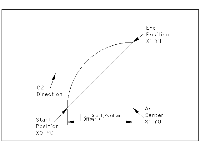
Figure 1. G2 Example
In the next example we see the difference between the offsets for Y if we are doing a G2 or a G3 move. For the G2 move the start position is X0 Y0, for the G3 move it is X0 Y1. The arc center is at X1 Y0.5 for both moves. The G2 move the J offset is 0.5 and the G3 move the J offset is -0.5.
G2-G3 Example Line
G0 X0 Y0
G2 X0 Y1 I1 J0.5 F25 (clockwise arc in the XY plane)
G3 X0 Y0 I1 J-0.5 F25 (counterclockwise arc in the XY plane)
Figure 2. G2-G3 Example
In the next example we show how the arc can make a helix in the Z axis by adding the Z word.
G2 Example Helix
G0 X0 Y0 Z0
G17 G2 X10 Y16 I3 J4 Z-1 (helix arc with Z added)
In the next example we show how to make more than one turn using the P word.
P word Example
G0 X0 Y0 Z0
G2 X0 Y1 Z-1 I1 J0.5 P2 F25
In the center format, the radius of the arc is not specified, but it may be found easily as the distance from the center of the circle to either the current point or the end point of the arc.
5.3. Radius Format Arcs
G2 or G3 axes R-
-
R - radius from current position
It is not good practice to program radius format arcs that are nearly full circles or nearly semicircles because a small change in the location of the end point will produce a much larger change in the location of the center of the circle (and, hence, the middle of the arc). The magnification effect is large enough that rounding error in a number can produce out-of-tolerance cuts. For instance, a 1% displacement of the endpoint of a 180 degree arc produced a 7% displacement of the point 90 degrees along the arc. Nearly full circles are even worse. Other size arcs (in the range tiny to 165 degrees or 195 to 345 degrees) are OK.
In the radius format, the coordinates of the end point of the arc in the selected plane are specified along with the radius of the arc. Program G2 axes R- (or use G3 instead of G2). R is the radius. The axis words are all optional except that at least one of the two words for the axes in the selected plane must be used. The R number is the radius. A positive radius indicates that the arc turns through less than 180 degrees, while a negative radius indicates a turn of more than 180 degrees. If the arc is helical, the value of the end point of the arc on the coordinate axis parallel to the axis of the helix is also specified.
It is an error if:
-
both of the axis words for the axes of the selected plane are omitted
-
the end point of the arc is the same as the current point.
G2 Example Line
G17 G2 X10 Y15 R20 Z5 (radius format with arc)
The above example makes a clockwise (as viewed from the positive Z-axis) circular or helical arc whose axis is parallel to the Z-axis, ending where X=10, Y=15, and Z=5, with a radius of 20. If the starting value of Z is 5, this is an arc of a circle parallel to the XY-plane; otherwise it is a helical arc.
6. G4 Dwell
G4 P-
-
P - seconds to dwell (floating point)
The P number is the time in seconds that all axes will remain unmoving. The P number is a floating point number so fractions of a second may be used. G4 does not affect spindle, coolant and any I/O.
G4 Example Line
G4 P0.5 (wait for 0.5 seconds before proceeding)
It is an error if:
-
the P number is negative or not specified.
7. G5 Cubic spline
G5 X- Y- P- Q-
-
I - X incremental offset from start point to first control point
-
J - Y incremental offset from start point to first control point
-
P - X incremental offset from end point to second control point
-
Q - Y incremental offset from end point to second control point
G5 creates a cubic B-spline in the XY plane with the X and Y axes only. P and Q must both be specified for every G5 command.
For the first G5 command in a series of G5 commands, I and J must both be specified. For subsequent G5 commands, either both I and J must be specified, or neither. If I and J are unspecified, the starting direction of this cubic will automatically match the ending direction of the previous cubic (as if I and J are the negation of the previous P and Q).
For example, to program a curvy N shape:
G5 Sample initial cubic spline
G90 G17
G0 X0 Y0
G5 I0 J3 P0 Q-3 X1 Y1
A second curvy N that attaches smoothly to this one can now be made without specifying I and J:
G5 Sample subsequent cubic spline
G5 P0 Q-3 X2 Y2
It is an error if:
-
P and Q are not both specified
-
Just one of I or J are specified
-
I or J are unspecified in the first of a series of G5 commands
-
An axis other than X or Y is specified
-
The active plane is not G17
8. G5.1 Quadratic spline
G5.1 X- Y- I- J-
-
I - X incremental offset from start point to control point
-
J - Y incremental offset from start point to control point
G5.1 creates a quadratic B-spline in the XY plane with the X and Y axis only. Not specifying I or J gives zero offset for the unspecified axis, so one or both must be given.
For example, to program a parabola, through the origin, from X-2 Y4 to X2 Y4:
G5.1 Sample quadratic spline
G90 G17
G0 X-2 Y4
G5.1 X2 I2 J-8
It is an error if:
-
both I and J offset are unspecified or zero
-
An axis other than X or Y is specified
-
The active plane is not G17
9. G5.2 G5.3 NURBS Block
G5.2
X- Y-
...
G5.3
Warning: G5.2, G5.3 is experimental and not fully tested.
G5.2 is for opening the data block defining a NURBS and G5.3 for closing the data block. In the lines between these two codes the curve control points are defined with both their related weights (P) and the parameter (L) which determines the order of the curve.
The current coordinate, before the first G5.2 command, is always taken as the first NURBS control point. To set the weight for this first control point, first program G5.2 P- without g